Take One Giant Step---And get started on a steam car of your own make. Build this little EDUCATOR as the first Giant Step toward the ultimate in modern transportation, a modern Steam Car.
In 1965 Richard J. Smith of Midway City, California designed and built a Speed Buggy primarily to demonstrate practical light steam power on a scale at which it would not only be achievable by the able amateur, but in a way that it would, by doing, teach the builder a great deal about the practical points of operating a steam power system. It was also a showcase for the deceptively simple and not previously very obvious method of direct mechanical control of the fuel and water by temperature and pressure, as described in Smith's patent.
Dick was spurred on in this work by Thomas P. Hall, publisher and editor of The Steam Calliope Magazine, "The Voice for Western Steam", started in 1965 as a regional publication of the Steam Automobile Club of America, but soon becoming Tom's proprietary publication. At this same time, Karl Petersen had left Rensselaer Polytechnic Institute with a graduate degree and, while working in Santa Monica, had sought out Tom Hall to find out what was hot in the steam car development field. Very soon he found Dick Smith and, in barter and appreciation for the generous tutorials Dick offered, participated in the final construction and demonstration of the Educator buggy and continued to work with Dick on steam car development, very soon a full time endeavor for both.
The Educator buggy had its first public outing at the Laguna Beach SACA meet in 1967, and was enroute to the Greensboro, North Carolina meet, in a trailer, when Dick, Karl, Carl Guth of Arizona, and the trailer were put off the road into an Alabama swamp by an errant motorist. The buggy was so thoroughly damaged, that the wrecked parts were dismantled.
While a converted 4-cylinder Mercury outboard with Smith rotary valve saw much service in the buggy, it also ran a Stuart Turner Double No. 1 constructed by Ed Puryear for the purpose. This was the most balanced and successful engine, even with its relatively high steam use, as it had a reasonable displacement with the 2" bore and stroke. This engine was sold to a paying customer, and the Merc conversion was installed in a VW bug along with a small demonstration steam generator and shown at Greensboro and other meets.
SPECIFICATIONS FOR THE EDUCATOR "SPEED BUGGY"
Total weight--450 pounds
Speed--Up to 40 miles per hour
Fuel--Low grade gasoline or diesel fuel, kerosene or paint thinner recommended.
Mileage--40 mpg plus
Warm up time from cold--One minute
Steam Generator -- Smith design water tube
Engine--Several alternates are suggested
Wheels--20" bicycle with balloon tires
Body--Plywood, 2 passenger plus 60 pounds of luggage
Feed water pump--Modulating, variable displacement
Burner--Smith redesign of stock item
Controls--Smith design, completely modulating
Drive--Friction type differential, two wheels powered, chain final drive
Brakes--Optional, internal expanding drum type or caliper type disc, two- or four-wheel mechanical
Throttle -- Foot accelerator to ball valve
GENERAL INSTRUCTIONS for "EDUCATOR" body
Bill of Material
1 4 x 8 sheet of ¾" Marine grade plywood with grain face of builders choice
1 4 x 8 sheet of ½" Marine grade plywood with similar face
2 1" x 2" x 12 Clear grade pine or fir lumber
2 2" x 4" x 36" Clear grade pine or fir lumber
2 2" x 4" x 10 Clear grade pine or fir lumber
4 3/8" x 4" Carriage bolts
1 1/8" x 1-1/4" x 10 Strap iron
42 ¾" #8 Flat head wood screw
18 1-1/4" #8 Flat head wood screw
36 1-1/2" #8 Flat head wood screw
1# 2" Finish Nails
These drawings of the car body are quite simple and self explanatory. The construction is simple enough that the average individual should have no difficulty in cutting out the parts and assembling the few pieces that make the total body. The individual builder will probably have some ideas of his own as to exactly how he wishes to finish the wood. He may wish to paint it black or he may rather buy a better grade of material like walnut or oak or any one of a dozen fine-faced woods.
Common tools usually found in the average home workshop will be of the class of tools required to do a fine job. A table saw or an electric hand saw will come in handy but is not required. For the curves, a sabre saw or a key-hole saw will serve equally well. After getting all of your material together and you have the body parts laid out and cut out, you can get the parts together and tack them in place. Then you can see how to properly fasten the various parts into a rigid structure. The liberal use of screws and a good grade of glue will make for a strong structure.
The power plant will require that a hole be cut in the floor under the seat. Servicing of the plant will be facilitated if the seat is removable, so do not glue it in place at this time.
Have fun building the body and dreaming of driving your own steam automobile.
Curve radius shown on the tailgate is 90-1/2". Each part should be labeled when cutting out. All carriage bolt holes require a counterbore with a diameter and depth which can accommodate the heads of the bolts. You may use elevator bolts if available as they pull flush with the face of the wood. Be sure the heads are flush with the framework, as they will be covered by the 1/2" plywood floor.
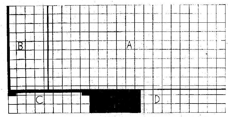
Obtain a 4' x 8' sheet of 1/2" marine plywood. Lay out in 4" squares. Carefully transfer lines to plywood as shown below. Shaded areas are waste. "A" denotes floor, 37 1/2" x 78". "B" denotes seat, 37 1/2" x 16 3/4". "C" denotes rear deck support, 36" x 9 3/8", notched to fit frame rails as shown. "D" denotes rear deck, 37 1/2" x 10 1/4". Rabbet one long edge, 1/4" x 3/4" x 37 1/2" to fit part "F" on the 3/4" material layout. Parts "C" and "D" below are omitted on the exploded drawing for the sake of clarity. They form the rear section of the power plant.
Obtain a 4'x8' piece of 3/4in marine plywood and lay out in 4in squares. Carefully transfer lines to plywood from pattern as shown below. Dark areas are waste. A and A' denote body sides. Extreme overall dimensions are14-1/4 x 78in. B and B' denote side railings, 4 x 24in. C and C' denote seat sides, 5 x 18in. D denotes the seat back, 5 x 42in. E denotes front (inclined) nose piece 8 x 37-1/2in, E denotes top nose piece 1-1/4 x 37-1/2in. G denotes kick panel 10-1/2 x 36in. H denotes tail gate 11 x 36in (90-1/2in radius). J denotes back rest 5 x 36in. K denotes top nose piece 4 x 37-1/2in. Check all critical dimensions while laying out. Saw carefully with fine or medium blade to prevent splintering. Raw edges may be finished with wood putty, veneer strip, or metal edging where applicable. It is suggested that the wood surfaces be finished when the car is completed, however primer or sealer may be applied at this time.
It is recommended that all parts be tacked in place with finishing nails first. Then drill and countersink all the screw holes. The seat frame assembly will recess into a rectangle formed by the car sides, the kick panel and the stretcher but DO NOT attach the seat or the seat frame to the car body. It must be removable to service the power plant.
A second stretcher, not shown on the exploded plan, 1" x 2" x 36" , must be used between the rear deck piece and the rear deck support. These three pieces form the housing for the rear section of the engine compartment. Fastening the seat back straps between frame doubler and stretcher, not shown on plan, will make it easier to remove the rear housing, if and when necessary. Do not install the 3/4" plywood parts E and K at this time. The brake and the control pedals should really be installed before the nose pieces.
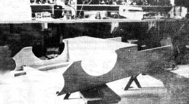
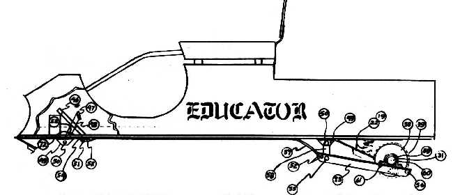
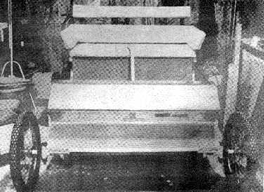
This picture shows the EDUCATOR'S body during construction.
SUSPENSION SYSTEM
Bill of Material
4 Heavy duty 20" bicycle wheels
2 3/4" pipe flanges
4 12" heavy duty barn door hinges
1 Set of 2 Evenride Shock Springs, Model 5I.
2 Steel plates, 6 1/4" diameter, 1/4" thick
1 Steel plate sprocket, 60 tooth for #35 roller chain.
4 2 3/8" chain link fence post caps
3ft 1" x 1/4" steel strap
2ft 1 1/2" x 3/8" steel strap
2 7/8" x 6" steel bolts
2 3/4" x 4" steel bolts
1 3/4" x 6" sttl bolt
12 1/4" dia. steel bearing balls
1 3/4" x 4" pipe nipple
8 1/2ft 1 1/2" dia steel pipe
4 ft 1" dia steel pipe
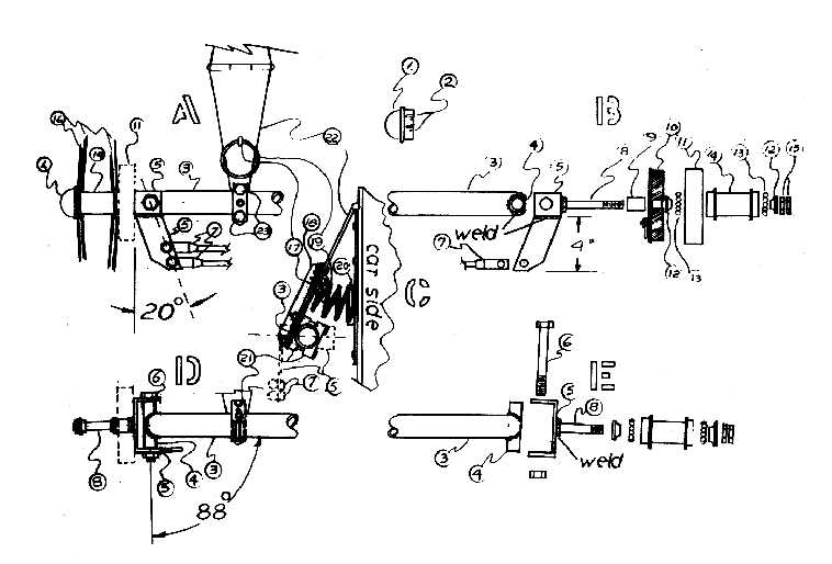
1. Hub cap, 2 3/8" fence post cap.
2. Slots to accept spokes.
3. Front axle, 1 1/2" x 44 1/2" steel pipe, slot ends to accept king pin bushings as shown.
4. King pin bushing, 3/4" x 3" long steel pipe. Weld accurately and securely to axle.
5. Spindle and steering arm assembly. Spindle carrier and steering arm formed of 3/8" x 1 1/2" steel strap. Carefully drill parts for kingpin.
6. 3/4" x 4" bolts and standard 3/8" tie rod ends.
7. Spindle.
8. is a 7/8" dia. bolt, the length depends on the stacked height of components as in view "A" with the brake (as required by vehicle code) or in view "E". The stack in view "B" consists of 9 spacer, equal in length to 10 and 11 assembled.
10. Brake backing plate and shoe assembly. Bolt to spindle carrier 5.
11. Brake drum. Braze to hub 14.
12. Bearing cone. Anneal, bore to 7/8" I.D. and reharden.
13. Stock ball bearing
14. Wheel hub.
15. Nut and lock nut.
16. Spokes.
Note! In View E we show the simplified version without the brake. We have omitted the items 9, 10 and 11, hence the spindle bolt would be 3 1/2" approximately.
17. Spring retaining clip, 8 required, form of 1/4" threaded steel rod.
18. Stiffener of 1" x 1" steel angle, 1 required.
19, 20, 21 and 23 are furnished with "Evenride Shock Kit".
19. Spring. Two long springs supplied with kit. Saw 5 turn coils from each spring. Close cut ends by heating and bending.
22. 12" heavy duty barn door hinge.
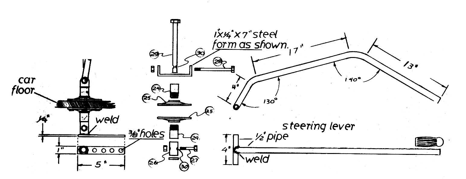
24. 3/4" pipe, 1 1/2" long, threaded.
25. 3/4" pipe flange.
26. 3/4" pipe. 1 1/2" long.
27. 3/8" bolt, 1 3/8" long
28. 1/2" bolt, 5" long.
29. 3/4" bolt, 6" long.
30. Hole, to suit 27.
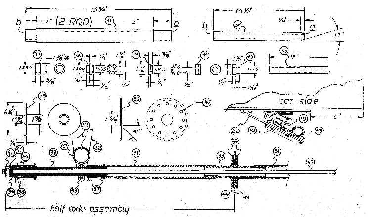
31. Axle, inboard, 1 1/2" pipe, turn ends to 1 7/8" dia., bore ends 1.625" dia. 4 1/2" deep.
32. Axle, outboard, 1" pipe. Turn to 1.250 dia. full length. End "a" to suit "Bendix" type hub 14, two required.
37. Spacer ring. Weld ring, 1/2" in from end "b" of 32. Weld 2nd ring 3 7/8" center to center from 1st ring. Mount assembly in lathe. Rough turn to 1 7/8" dia. and finish turn for a close fit into end "b" of 31. Braze in place. 4 rings required. Braze differential disk 38 to the end "a" of 31. Straighten half axle assembly and clean up face of 38 in the lathe.
38. Sprocket carrier, 1 1/4" pipe. Turn to 1.625" dia. (nearly) for a slip fit into the end "a" of 31.
39. Sprocket. 60 tooth for #35 chain. Drill twelve 17/64" dia. equal spaced holes on a 5 3/4" circle. Bore 1 5/8" hole for close fit to 33. Chamfer to 1/8" depth. Locate in center of and square to 33. Braze on chamfer side only. Components are assembled as shown.
34. Ball thrust bearing #52772-1-3 is fitted between 34 and 45.
44. 1/4" steel balls, surfaces of 32, 33, 34, 38 and 39 should be lightly coated with Lubriplate before assembly.
43. Bearing is Fafnir RA-103NPPB2, 1 1/4" bore, 2 required.
42. 1/2" dia. tension rod. Nut is welded to end (not shown). Rod passes through 35, thence through entire assembly to adjusting nut 41.
41. Nut is tightened until tires can be skidded without slippage occurring between 39 and 44.
Simple shouldered bushings of nylon or bronze are used as bearings between 4 and 6, 24 and 29.
26. is intended to fit loosely on 29.
You should be looking for a set of four 20" REAR, heavy duty bicycle wheels with balloon tires. The wheels will best be built up with heavy duty spokes, rims and tires. Few bicycle stores carry these in stock but will order the parts and build to suit the customer.
The new type (proprietary) ball bearing differential as shown above is rugged, simple to build, and has a semi limited slip characteristic. With reasonable care, you should have no difficulty handing the machine work on a light 12" lathe.
When attaching the steering assembly to the car floor, be certain that its position does not interfere with the normal movements of the front axle assembly.
46. Toe board, 1" x 8" plywood, fasten to car sides, floor, and cross member. Slot 46 and floor to accommodate 18 and its movement.
47. Pedal, 3/8" x 1 1/2" x 3" steel. Weld at center to 48 as shown.
48. 3/8"x1 1/2" x 7" steel, cut one end at 45 angle for 47, drill 3/8 hole for 50, 3/8" from other end, drill to suit 72, 2" from 3/8" hole.
49. 1 1/2" steel angle 4" long, cut two corners, 45 angle, drill 3/8" hole for 50 in center as shown. mount to car floor with two 3/8"x1" bolts, four req'd.
50. 3/8"x5/8" stripper bolt, two req'd.
51. 1" steel angle. Drill & tap center, one surface to suit 52, fasten to floor with tow 3/8"x1" bolts.
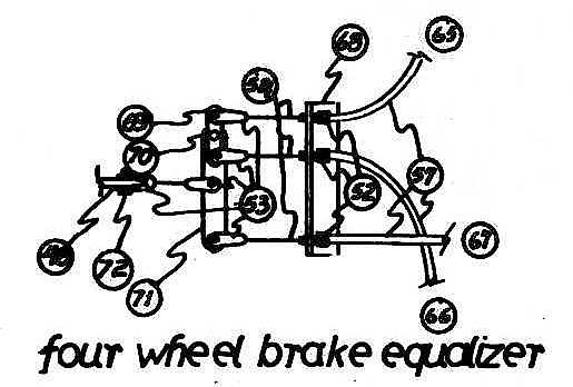
52. Brake cable adjuster, obtain with 54 and 37.
53. Cable end clevis, one req'd for rear brakes only, five required for four wheel brake setup.
54. Heavy duty brake or clutch cable, as used on motorcycles.
55. 3/8"x1 1/4" stripper bolt.
56. 3/8" x 1 1/2" heat treated cap screw.
57. Cable housing, as supplied with 54, cut to suit application and attach fittings as req'd.
58. Reaction link, 3/8"x1 1/2" x 4" steel. Drill 3/8" hole, 3/8" from each end.
59. 1/4" x 1" steel, form as shown to freely accommodate 60 when in place. Fasten to 73 with 1/4" x 3/4" bolts 61 as shown.
60. 1 1/4" to 1 1/2" wide leather or webbing (such as used in the Model T Ford transmission). Bond to axle next to 38, lightly grease.
62. Nut and locknut for 55.
63. Not shown, light coil or curved washer, springs, on both sides of 58 for centering.
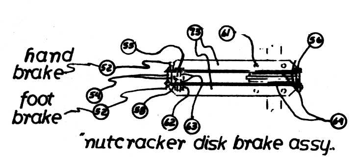
64. Brake lining pads. Bond or rivet to 73 as shown.
65. Cable to left front brake.
66. Cable to right front brake.
67. Cable to rear brake.
68. 1" steel angle 4" Body is threaded 7/16-32 through. Drill and tap three places to suit 52. Fasten to car floor with 3/8" x 1" bolts.
69. 1/4" x 3/4" x 2 1/2" steel. Drill 3 holes to suit 72 (clevis pins), one in center and one 1/4" from each end.
70. Washer separates 69 from 71, allowing free movement.
71. 1/4" x 1" x 4" Body is threaded 7/16-32 steel. Drill three holes to take 72, one in center and one 1/4" from each end.
Note! Some states require four wheel brakes even on light weight cars. Check with your local department of motor vehicles.
Note! Drum brakes for the front may be obtained from your local go-kart or scooter shop.
73. "Nutcracker" reaction arms are of 1 1/2" steel angle, 18" long. Drill holes as shown to accommodate previously described applicable parts and allow for the proper movement of the parts without interference. Adjust bolts 55 and 56 so that arms are parallel and pads 64 are just touching sides of 38. Remove cable slack with adjusters 52 and lock all adjustments. A hand brake lever, not shown, may be obtained at your local junkyard and fitted in a convenient location. Parts such as 49 and 51 will be useful in applying. Connect to rear brake as shown.
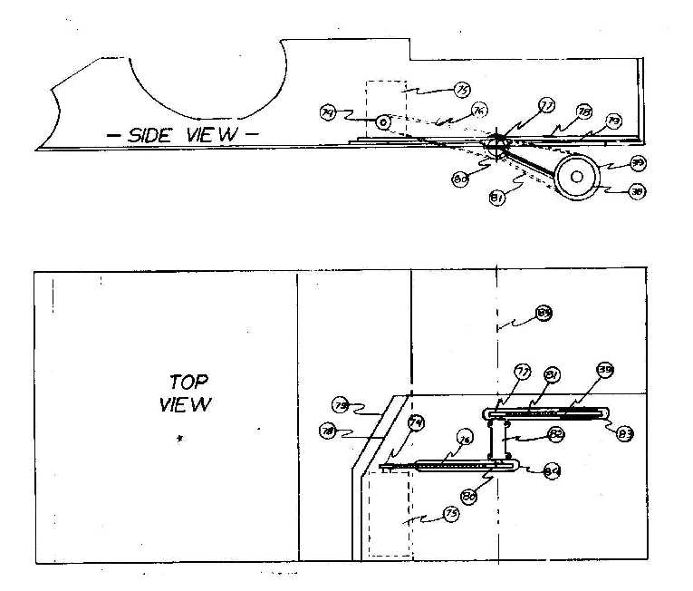
75. Engine Sprocket
76. Primary Chain
77. Secondary Drive Sprocket
78. Doubler, 1/2" plywood
79. Full size plywood spacer
80. Primary driven sprocket
81. #35 final drive chain
82. Ball bearing saw arbor
83, 84. Slots to permit chains to pass through floor. Dimensions
to suit your particular installation (engine crank height, etc.).
85. Center lines of 82 and hinge pins must coincide,
adjust thickness of 79 to suit.
82. is fastened to 78.
Make chain guards to suit.
Make all fastenings with screws and bolts.
THE ENGINE
Now, we will discuss the type of engine which would be suitable for use in the EDUCATOR. We must keep the cost to a minimum in order to meet our quoted cost of $495.00 for the entire vehicle. To do this we must choose a low cost item and do most of the work on it ourselves to keep the money 'in the family' so to speak.
For those who wish to machine from ready-made castings, it is suggested that the Stuart Turner casting sets be purchased. The size engine that is recommended is the No. 1 with bore and stroke of 2"x 2". In order to have a self starting engine of adequate power, you will need two engines and couple them together with a chain or sleeve. Both engines being mounted on a common base.
It is further suggested that the engines be enclosed in a dust tight compartment with the drive shaft protruding far enough to permit the mounting of a drive sprocket by which to drive the jack-shaft shown in a previous issue. The enclosure should be of sheet metal with a door conveniently located for inspection and oiling as many people will want to see the 'workings.
As a minimum engine, it is suggested that the Stuart No. 4 or 9 be used. It should be remembered that the labor involved in building a pair of these engines is almost exactly the same as that required to build a pair of the larger and recommended engines, therefore we strongly I urge you to consider only the 2"x 2" size.
The Stuart Turner engines in kit or completed form may be purchased from Cole's Steam Models, Ventura, California.
For those who would prefer to convert existing IC engines such as a Briggs & Stratton to steam, it is suggested that possibly, in your area you can find a pair of old lawn-mower engines that could serve as the basic power plant. Often, these can be had for a little more than the effort required to haul them away. You will not need the fuel system or the exhaust pipe or the head. Just be sure that you get two of the same model. These old cylinders will serve as the crosshead guides for a double-acting engine. Stuart No. 1 cylinders can be used as the steam cylinders. This arrangement will cut down on the amount of machine work required.
This is beginning to get disgusting. We ordered the burner assembly from Montgomery Ward some time ago and just received a notice that they will not even ship it until the 20th of January. In that we do not have the burner and thus are not aware of its flame pattern, we cannot properly proportion the combustion chamber space. We have, however, determined the amount of materials required to build the steam generator. Those who are building this generator are advised to obtain the following:
200' of 1/4" O. D. copper tubing - standard grade - . 031 wall
25' of 5/16" O. D. copper tubing - standard grade - . 031 wall
2-1/2 of 5/16" O. D. stainless steel - 300 series - . 020 to . 035
wall (a straight section)
1 sq. yd. of heavy duty high temperature insulating fabric (Cerrofelt)
1 3 x 4 sheet of 26 gauge steel. It may be blued, nickeled, Stainless
or just plain black iron.
50' (approx. ) of . 050 (approx. ) stainless steel wire 300 series.
1 weed burner - 2 gal. size - (see Montgomery Ward farm Catalog No.
89FB21282MS)
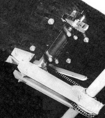
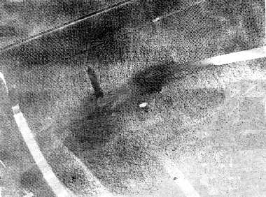
The underside of the EDUCATOR and the arrangement of the jack-shaft/chain drive from the engine to the axle.
THE BURNER
And how to build it from shelf ready parts.
This is not the best way to fire a boiler, but it is easy to control, and is fairly cheap. Its major fault is that it takes longer to start the burner than it takes to raise steam. Also, it is somewhat noisy.
When your 89FB21282MS Ward's "Flamethrower" (weed burner) arrives it will be partly disassembled. Instead of putting it together, we are going to further take it apart and make some alterations. First, remove the sheet metal hood by removing four screws. Remove the burner nozzle and carefully enlarge the nozzle orifice, using a .060 drill This should be done in a lathe to ensure straightness. Now, re-install the nozzle tip. Remove two small screws and nuts from the bracket and withdraw (endwise), the nozzle assembly, spreading the bracket open only as necessary. Heat and bend the fuel inlet tube as shown in the picture. Take care to avoid kinking the tubing. Re-install the assembly as shown, tightening the bracket screws securely. Cut a slot in the, side of the hood to accommodate a "Turner" heavy duty burner tip, #LP-242 (or equivalent), leaving a "tab or tongue". Install "Turner" pilot as a pre-heater burner in the slot and attach it to the tongue with a small gear-type hose clamp. Aim the pilot burner so that the flame will play on the far side (inside) of the main generator coil. Obtain a "Turner" (or equivalent) 'torch' which will supply us with a pilot valve and pilot burner, etc. Detach the supply tube from the valve and install the 5/16 compression union in its place. Install 2 1/2 feet of 5/16" copper tube to the other end of the union. Connect the free end of the copper tube to the valve, using the fitting supplied with the torch.
Several experiments were undertaken to adapt the weed burner to our use. In its final form it delivered the following results: With pilot on full, the main burner generated in 2 1/2 minutes and was capable of burning 6. 1 pounds of fuel per hour. (Diesel fuel= 115, 000 btu/pound). At the recommended 25 psi fuel pressure, this should give us approx. 5 hp. nominal.
The fuel system was based on a two-tank Coleman style Army field kitchen vaporizing burner. The little gage panel is from that also. One tank holds white gas, filled through a floorboard cutout. The other is filled with air from the filler valve on the little panel.
THE STEAM GENERATOR
As a prelude to describing the steps to take in the construction of the steam generator for the EDUCATOR, I would like to point out that this particular design is not necessarily the only design to use in this vehicle, but it is the simplest and easiest for the neophyte to construct and build controls for. Several years of experimentation have preceded the selection of this design for this particular application It should be remembered at this time that for a larger unit, say, for a full sized automobile, this is NOT the design to use. This device car be constructed with a minimum of tools and know-how, and will work very well. We know, because we have tested this design extensively.
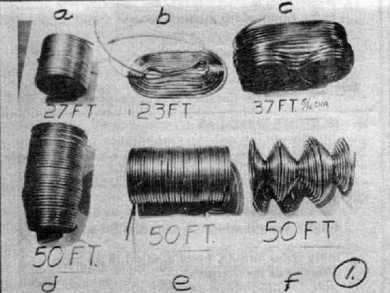
You may now refer to the step by step pictures. In photo #l. coils "a, d & e" were wound of 1/4" O. D. copper tubing over a 5" dia. form. In this case, a gallon paint can was used.) Coil "d" was necked down to 3 1/2" I.D. at one end by hand. Coil "b" is a flat pancake type of coil would by hand to fit inside a space 5 1/2" by 11 1/2". Coil "c" is the hard one to make. It is suggested that you tape two paint cans together, side by side, and form the tubing around then as shown. It may be a little difficult to form the reverse bends but care must be exercised to prevent flattening of the tube in the small radius area. As you proceed. these radii become larger and there-fore easier, please do watch the direction of winding in all coils. You will want all connections to be in the correct position when you have finished the coil winding. Coil "f" was formed as a series of flat pancakes by winding the tubing against itself, all coils touching, and then opened out as shown to leave gas passage spaces between the coils. This is your economizer section.
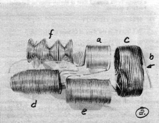
Photo #2 shows all of the coil sections in position for assembly.
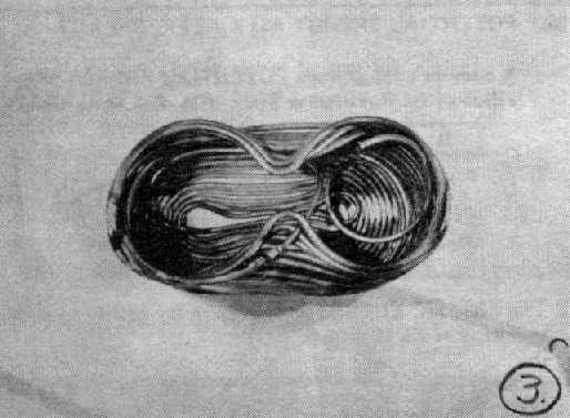
Photo #3 shows coils "b" and "c" assembled. Please note the connection and lay of the tubing.
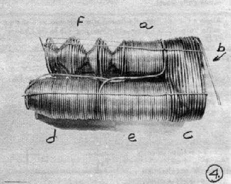
Photo #4 shows all sections joined by bell & spigot joints, brazed. Drive a 1/4" dia. dowel pin into one tube end and this makes the bell. The other tube will slip in for a fine brazing joint. All sections are now tied together as shown, using 1/8" dia. 300 series stainless welding rod and .050" stainless steel wire. Don't be stingy with the ties. You will note that the welding rods form a cage and the small wire is used as ties across the diameters of the coils. This prevents the coils from expanding like a Bourdon tube in a pressure gauge.
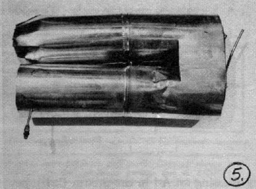
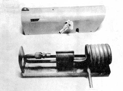
Photo #5 shows the inner covers in place. The author used bright stovepipe steel (tinned). A generous wad of asbestos fiber was stuffed into the "crotch" area to prevent the escape of hot gases. Then section "b" was covered with asbestos cloth and sheet steel.
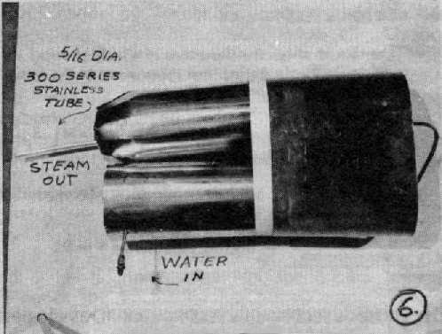
Photo #6 shows the completed steam generator with asbestos and steel covering the hot end. Our straight section of 5/16" stainless steel tubing is connected to section "c" by bell and spigot joint AFTER passing the tube through the combustion chamber. (Note: The stainless to copper connection should protrude 3" beyond the hot end of the generator for later control connections. )
To review the flow path of the water and steam through the various coil sections, just to be sure that you get them right the first time. The water goes in at the left end of ."f". From right end of "f" to the left end of "d". From the right end of "d" to the left end of "a". From the right end of "a" to the left end of "e". From the right end of "e" to the outer end of "b". From the inner end of "b to the left end of "c". From the right end of "c" to the straight piece of the stainless "steam Outlet". Be sure to leave the 3" protrusion for later control connections.
THE CONTROL SYSTEM.
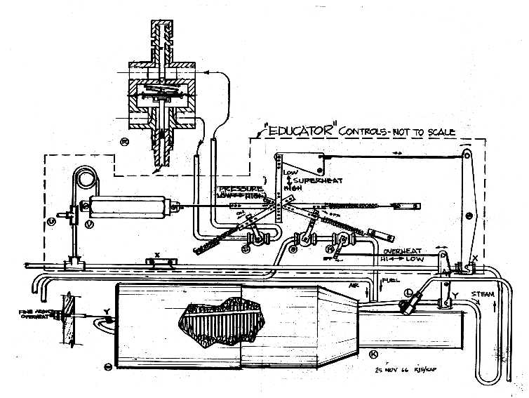
Control System Diagram
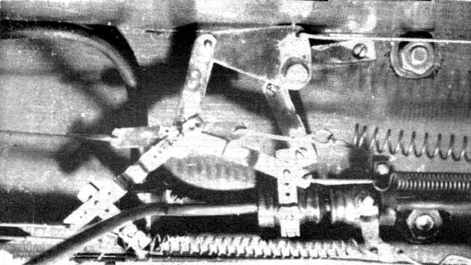
Control System Linkage
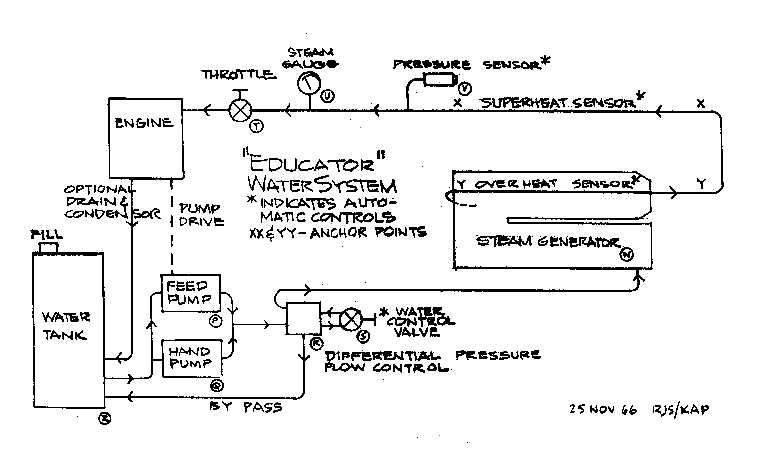
Water System Diagram
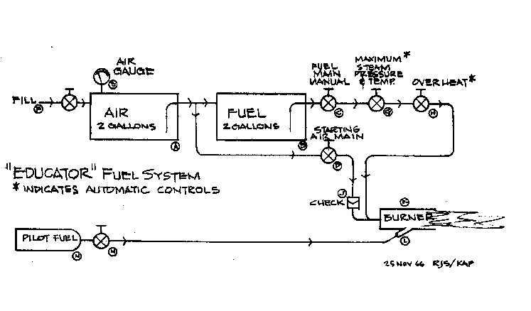
Fuel System Diagram
Primary Control Valve. Three required.
1. 1/8"dia. brass rod, groove as shown, and mill flats on one
end to fit slot in ball.
2, 6, 9. Teflon seals, machine to fit.
3. Gland nut, 5/16 hex brass. 1/4-40 EF thread (as used on miniature
toggle switches.
4. Stem guide, 1/4" dia. brass. Press fit to body.
5. Body, 5/8" hex brass, ream 3/8" dia. through.
7, 10. Adapter bushings, drill through 3/16", press fit to body,
drill and tap to suit pipe work.
8. 3/8" dia bronze ball. Ream 3/16 through, slot to receive
stem.
This valve has been tested in service for several years and is a proven design, for pressures to 500 psig and 400F.
At one time this valve could be obtained from Cole's Power Models, P.O. Box 788, Ventura, California.
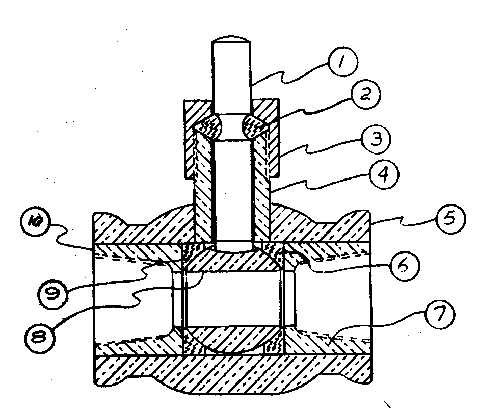
Differential Pressure Flow Control Valve.
1. Outlet, feed to steam generator.
2. Diaphragm, elastomer impregnated fabric, such as used in
propane regulators.
3. 1/8" dia. flow passage (two places)
4. Inlet port from feed pump.
5. 1/8" brass nipple, plug, drill and ream 3/32" dia.
6. Drill and tap body for six #6-32 socket head cap screws as
shown.
7. Bypass outlet, may be used to control pump output.
8. Body, 1 3/4" hex brass, machine as shown.
9. Outlet to primary water control valve.
10. Metering pin, 302 stainless steel, 3/32" dia. body x 1"
long, 5/16" dia. head, 1/31" thick, close slip fit to 7. Make "v"
notch end as shown.
11. Saddle, form of 1/32" brass, braze to lower diaphragm plate,
provide loose fit for head of metering pin.
12. Upper diaphragm plate. Plates are formed of 1/32" brass
to 1 1/16" diameter. Flare edges to protect diaphragm. Lower plate is furnished
with #6-32 stud for fastening to upper plate through diaphragm. Light (2
to 6 oz.) stainless steel spring loads the diaphragm downward. Diaphragm
requires 1/4" free travel.
13. Inlet from primary water control valve.
14. Ports (6) are all 1/8-27NPT.
15. Surge damping screw, may be left open or partly closed to
prevent pulsation. Screw is threaded #12-24 and is provided with screwdriver
slot.
16. 1/8" brass nipple, drill and tap #12-24.
17. 1/8" brass pipe cap.
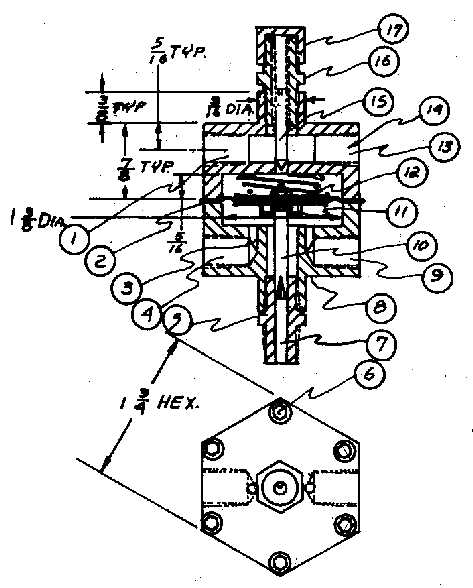
Throttle Valve
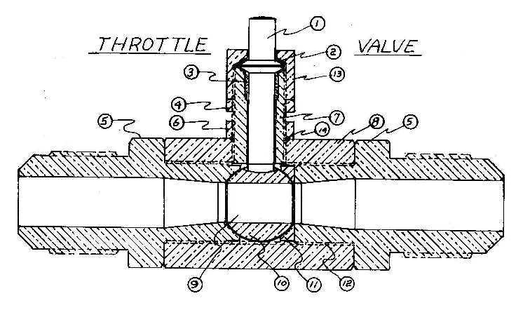
1. Stainless steel (302) stem. Machine thrust collar as shown
and mill flats on end to engage ball.
2. Teflon thrust washer.
3. Teflon stem packing.
4. Lock nut.
5. Standard 5/16" flare fittings altered as shown.
6. Lock nut. Chamfer as shown for seal 14.
7. Stem guide, 1/4-10 thread full length.
8. 5/8 hex body.
9. 3/16" dia. hole.
10. Body is threaded 7/16-32 through. 3/8" dia. ball. Mill slot
as shown to suit stem.
11. Floating seal.
12. Body is threaded 7/16-32 through.
13. Thrust nut
14. Lock nut to body seal (Teflon).
Note: Ball to seal clearance .002 +.001
All parts are brass or bronze unless otherwise noted. Workmanship must be first class on parts 1-5, 10 and 11 or the valve will leak. Parts 5-10 and 11 must match to very close limits.
This valve has proven itself over several years use in temperatures from -256F to over 950F and with pressures up to 10,000 psi.
FEED WATER PUMP (HIGH SPEED)
1. Check valves, "Circle Seal" 2259B, 1mm is recommended for pressures up to 250 p.s.i. #23498-1mm is recommended for higher pressures, soft rubber or plastic hose is recommended for inlet connection
TEST RESULTS.
Using the burner described in a previous installment in this series, a certified scale for weighing the water, a pressure gauge a stop watch and a variable displacement pump, the following data were obtained:
After the burner was started; first steam from water at 68F was made in approximately five seconds.
Operating pressure= 225 psig (mean)
Operating temperature (steam)= 400F.
Evaporation rate= 80 pounds/hour.
Stack temperature= 200-250F.
Fuel used= Cleaning solvent.
Date of test= 3/29/66
Test Engineer= R. J. Smith.
(Water was mixed with 1% soluble oil. )
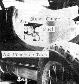
These two pictures are pretty well self explanatory except to say that they show the only manual controls to worry about on the EDUCATOR. The air and fuel valves are adjusted only at the start and end of your trip, and then all you have to do is turn them on or off. The steam gage is for reference only. It need not be on the dash board.
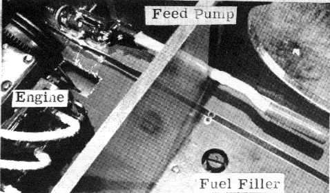
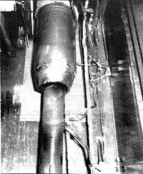
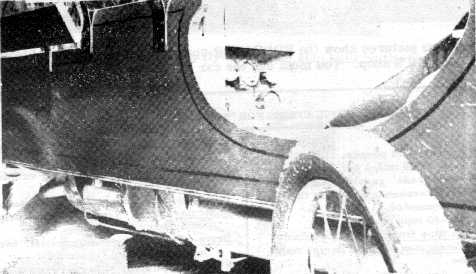
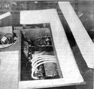
This picture shows the arrangement of the engine, fuel filler and the hand pump that was put on the car before a power operated pump became available.
This picture is for information only and shows how the rug is fitted around the pedals and steering tiller in the prototype EDUCATOR.
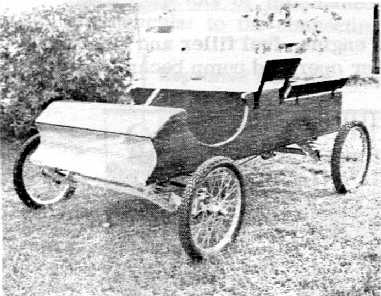
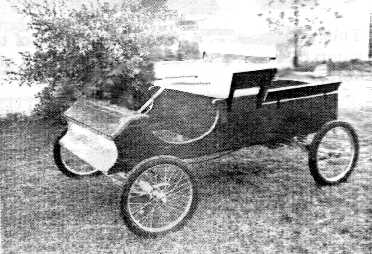
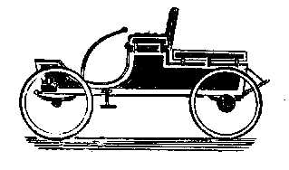
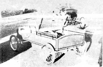
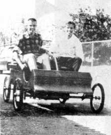
This pair of pictures show the EDUCATOR as it looks when finished. It is a pretty slick appearing buggy. It is ideal as a second car to run to the store or take the kids to school in. Whereever it is driven it is a traffic stopper. Every one asks what it is, how it runs, how fast will it go, how many mpg, and what kind of fuel. The really important question is, where can I get one? When people are told that it is home built, they won't believe it! The prototype is painted a candy-apple-red and is truly beautiful. When it takes off, people are amazed at the great pick-up and the silence. This unit being non-condensing, there is a little noise but if a condenser were added it would be perfectly silent as an electric car.
Final black pinstripe work by Sue Smith.
Bob Noble and Karl Petersen in the alley.
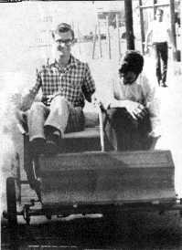
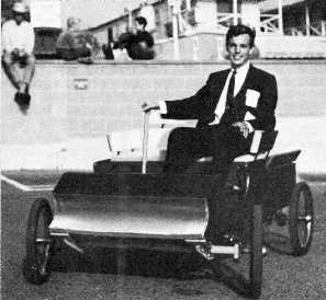
Karl gives a visitor a ride in the alley. Dick walks behind. Karl Petersen demonstrates at the Laguna Beach meet.
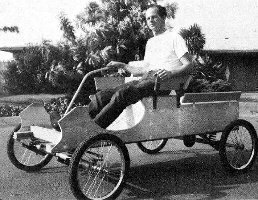
Richard J. Smith shows off the completed chassis.
This page powered by ![]() last updated 25 May 2024. Copyright © 1998-2024 Karl A. Petersen.
last updated 25 May 2024. Copyright © 1998-2024 Karl A. Petersen.