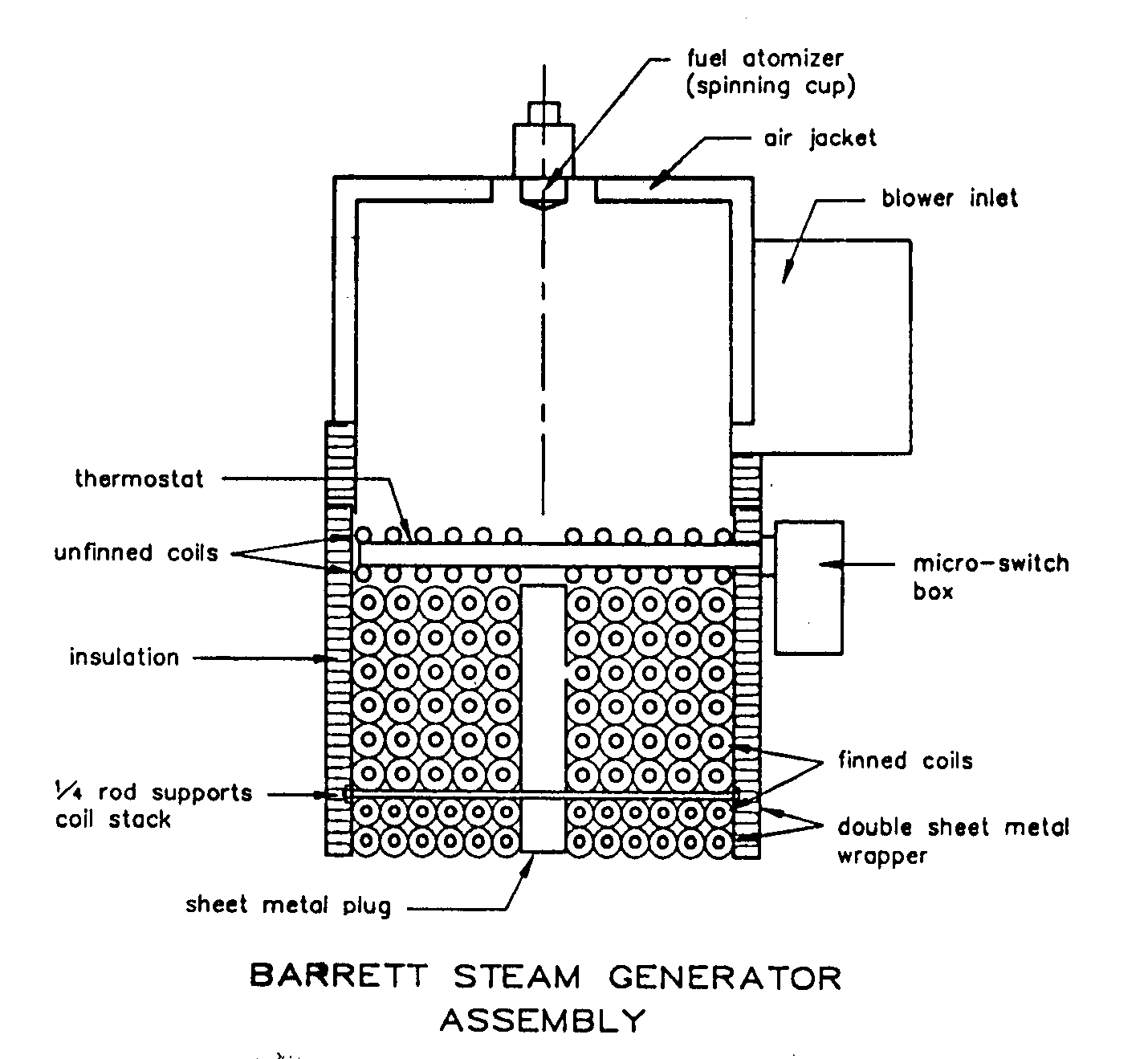
Here is a brief description of the steam generator. Air is delivered from a blower through an air jacket to the top of the combustion chamber. The air jacket provides cooling for the inner skin of the combustion chamber and preheats the air as it flows to the combustion chamber. The fuel is dribbled onto a spinning cup which vaporizes the fuel into a very fine spray. Only 12 watts of electric power is required to vaporize the fuel with the spinning cup. This is far less than would be required to vaporize the fuel with a pressure pump or compressed air. The coil stack in the Barrett steam car uses finned tubing. The finned tubing has 8 to 10 times the heat transfer surface of bare tubing. The coil stack with finned tubing is considerably smaller than a bare tube coil stack. The coil stack contains stainless tubing in which all joints are welded. As such the coil stack can withstand a considerable amount of abuse without damage. If the burner is turned on with a dry boiler, the over heat control will turn off the burner and no damage will occur to the coil stack.

The steam generator in the Barrett steam car is now functioning with excellent temperature control, so I have no reservations in recommending its duplication. Although for a long time the temperature control was unsatisfactory due to the location of the normalizer injection point, this problem has since been solved, and this article will explain what principles were used to solve it.
Perhaps the surest way to build a successful steam generator would be to build an exact duplicate of the one I have in my car. However, I realize many might like to design their own hardware, so I will try to describe general design principles in order that builders can make modifications to the design and still have a good operating unit, The assembly drawing shows the general arrangement of the steam generator.
The generator described in this article is based on the Doble configuration and has these features:
1. Counterflow of flue gas and water.
2. Combustion chamber above the coil stack.
3. Coil stack made from tubing wound into pancake coils.
4. Blower used to feed air to the combustion chamber.
![]() VW
Engine Conversion Drawing
sets available. Spinning
Cup Burner
VW
Engine Conversion Drawing
sets available. Spinning
Cup Burner![]()
This page powered by ![]() ,
created with Netscape Composer and last updated on 25 July 2019. Copyright
© 1999-2019 Karl A. Petersen.
,
created with Netscape Composer and last updated on 25 July 2019. Copyright
© 1999-2019 Karl A. Petersen.